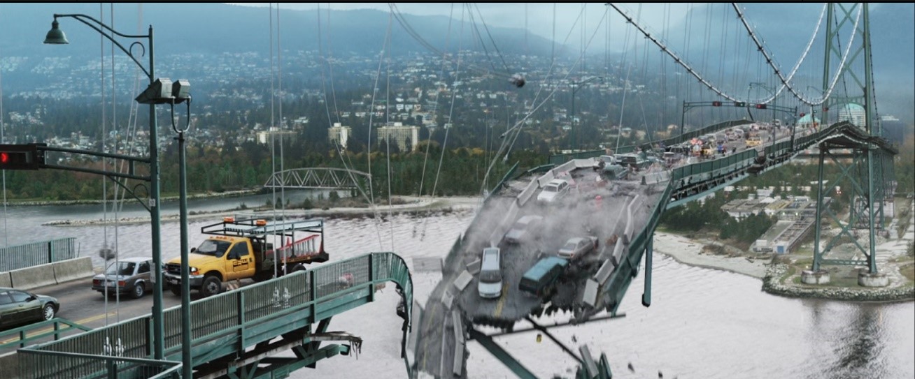
This project combined lots of different module techniques such as RBD simulation and vellum dynamics. The reference video is an excellent showcase of extremely accurate control of suspension bridge destruction since it displayed the whole progress of the bridge structure collapse. For me, it could be the most challenging project that I have ever done because the vellum module is an area that I have never explored before. Furthermore, another challenge could be the suspension bridge "swing" animation.
Reference
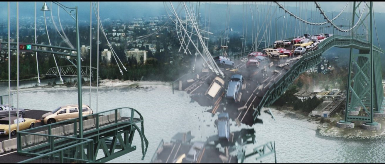
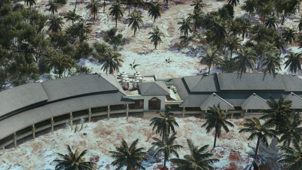
Render output
Techniques:
Animated RBD Optimization & Constraints setup
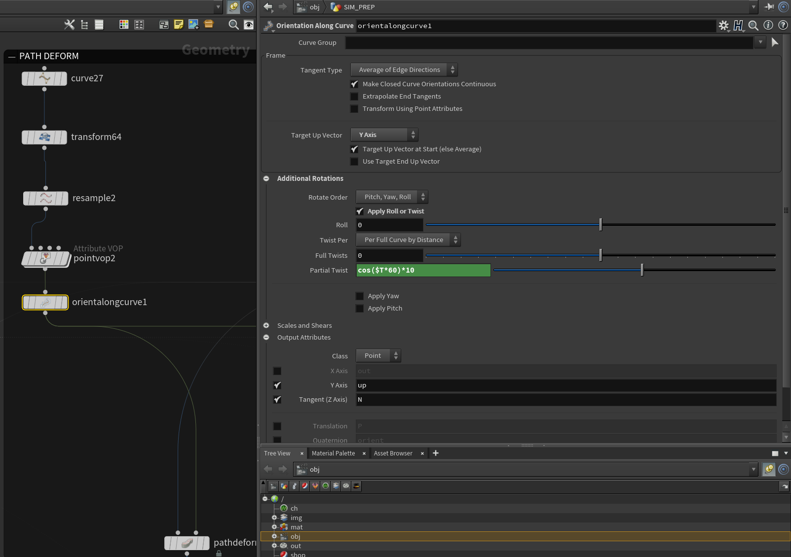
We can see the suspension bridge's back area from the reference video, the unbroken parts only following the swing movement. Instead of conducting a real simulation on that part, the bridge geometry is animated by a curve with sine and cosine expression in the horizontal direction and additional twist rotation along the curve to mimic that effects. As a result, the bridge model is mainly animated, which brings difficulties in fractures DOP simulation and the constraints position matching. However, the pre-fracture and constraints creation can be possessed before bringing back the animation using the "path deform" node after packing geometry since the packed geometry only records attributes in point class in most situations.
Path deforming animation
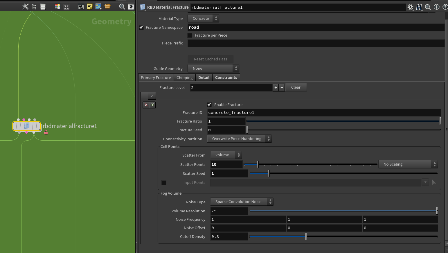
RBD Material fracture
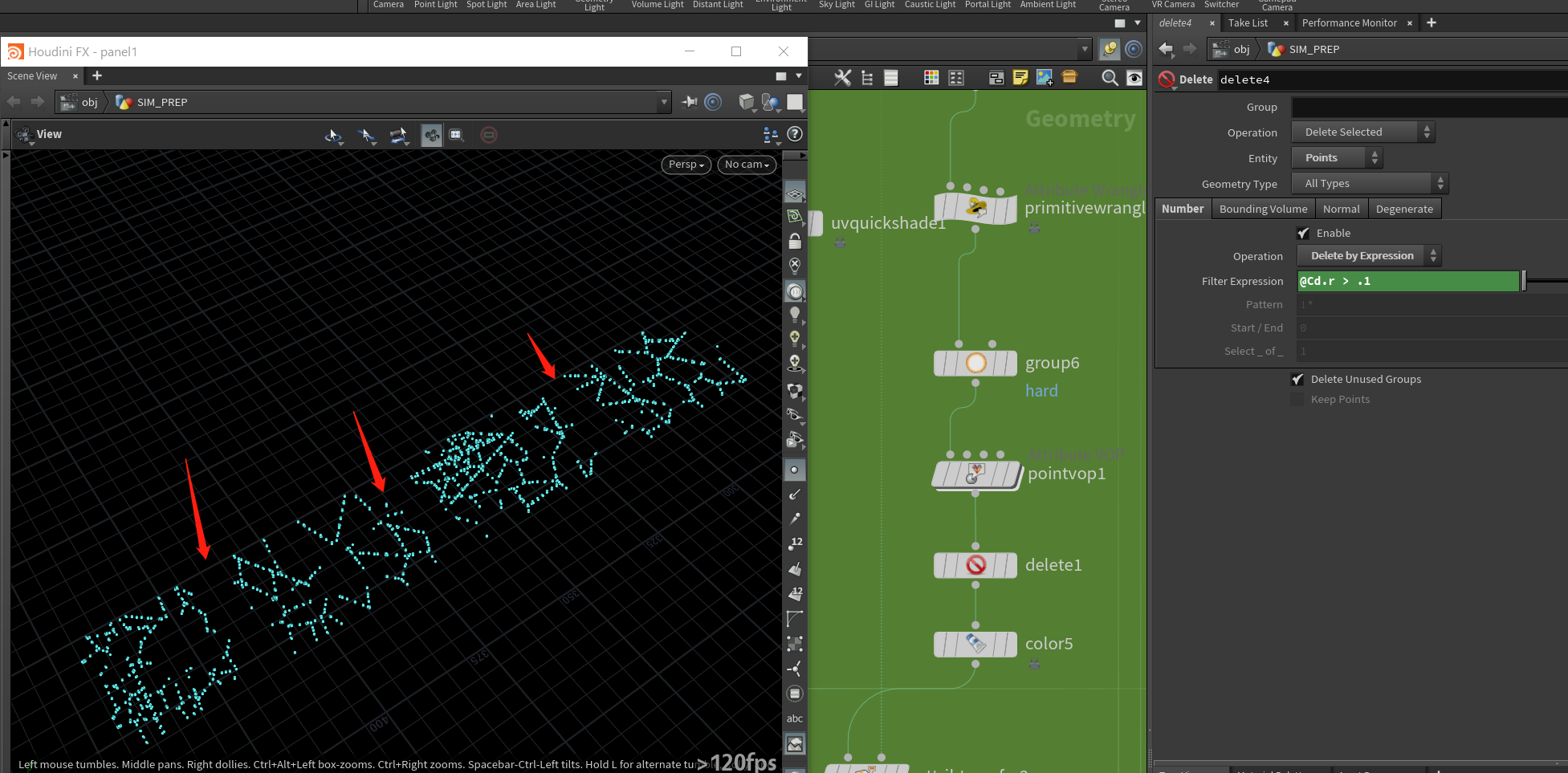
For each different parts of the bridge, it is necessary to create groups representing them separately for pre-fracture use. For example, the "road" group stands for the road surface. Referring to the video above, we can see there are "big chunks" when the main structure collapses while some debris following the dynamics. So, it is evident that constraints need to be attached to fracture pieces, and some of them should be deleted in the middle of the simulation. The node" RBD material fracture" can create boolean-fractured high-res shapes while exporting proxy geometry. However, we do need artistic control over the breaking threshold for the constraint geometry to create those "cluster" like effects. As a result, some displaced grids have been copied to specific locations to transfer color attributes for group delete purposes.
Customize constraints
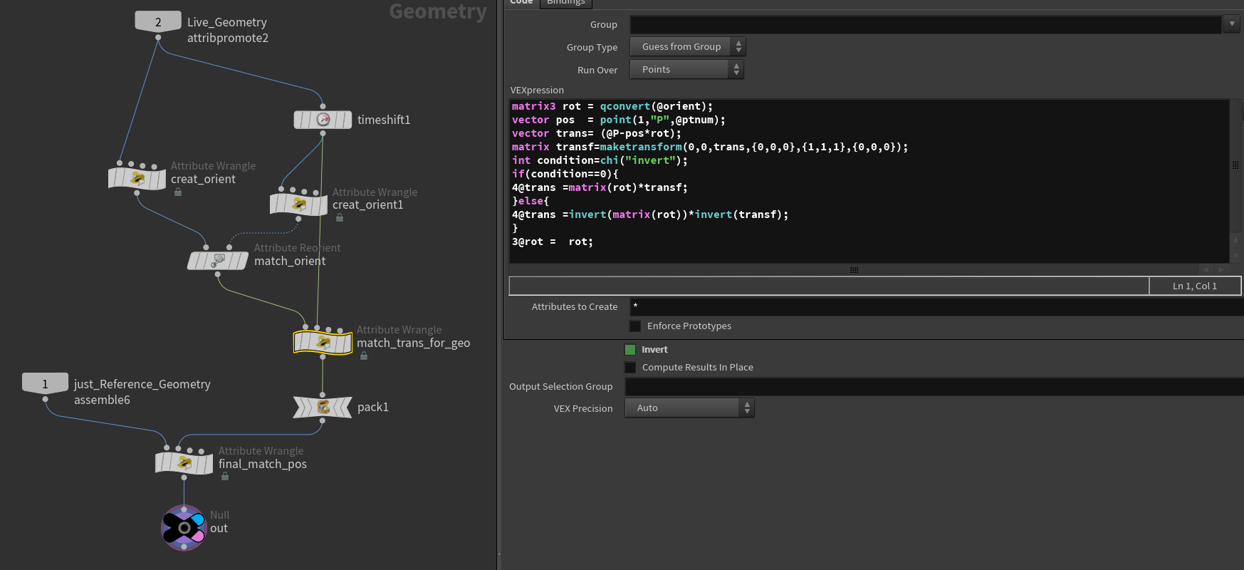
Because the fracture pieces have been animated at the Sop level, we need to keep the animation in the area where the RBD simulation does not begin. The "RBD packed object" node does provide some types for us to choose from, and the "animated static object" could be an appropriate option. The problem is that it only read animated objects with the active value set to zero, which means that it could bring in Sop animation, but the object cannot be solved. At the same time, the constraints also need to follow this path deforming animation. Since we need to customize constraints breaking threshold inside DOP network, the value of "Overwrite with SOP" under the "constraint network" node can only be enabled on the start frame. Thus, all these special requirements for the simulation should be met using another method——storing transforming matrix in the point level in packed geometry for rigid body solver. I manually created user attributes for calculating the transformation matrix based on piece names and transferred them to the point level, which made the pieces recognized by the rigid body solver as a "static object." However, they are moving each frame.
Re-calculate animation data and store at the point level
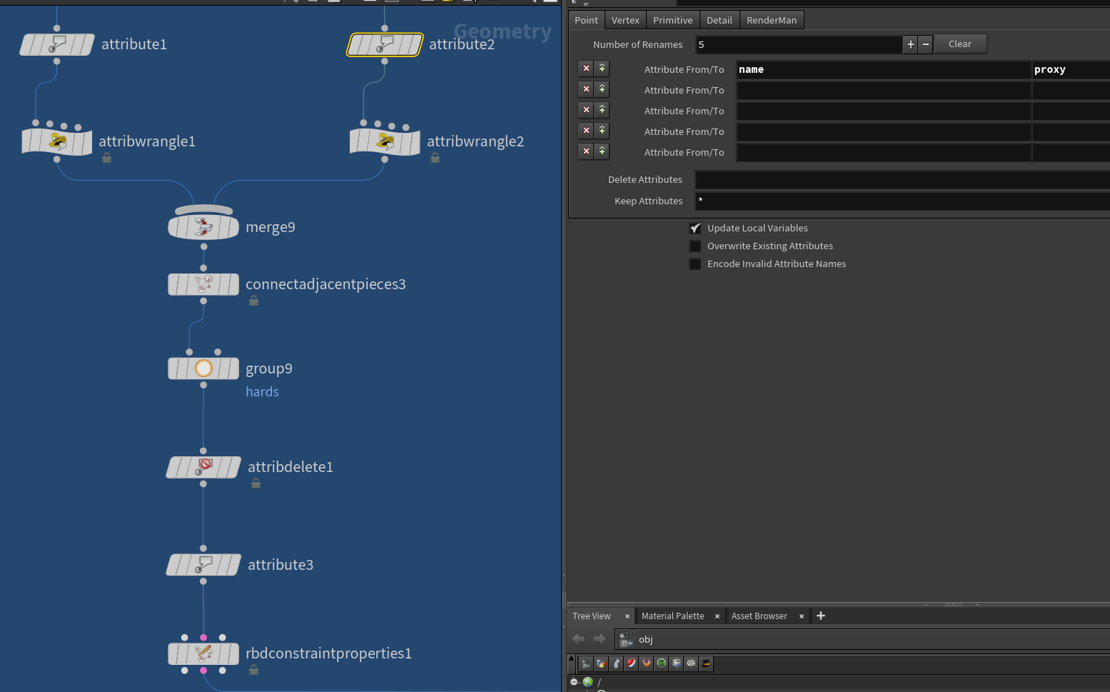
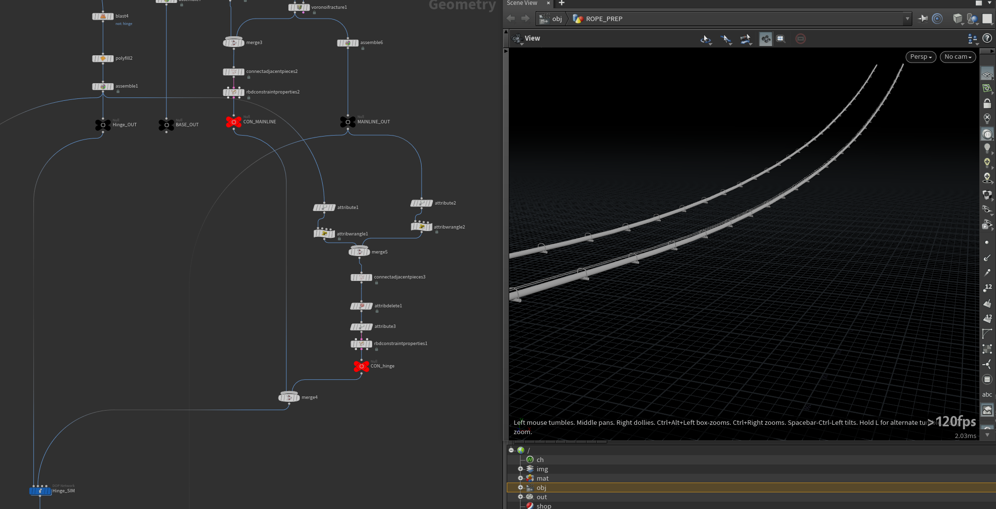
After finishing setting up for inner fracture constraints, it is time to think about the connections between different fracture groups. Because the constraints are based on the primitive "name" attribute, and we need to assign related "names" for closed pieces from input groups. In that case, the original "name" attributes from separate inner constraints need to be promoted to point level and restored after constraints between groups have been created.
Create constraints between groups
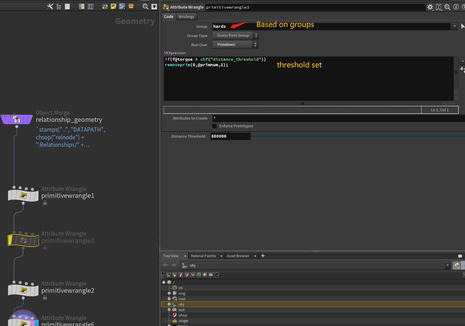
The soft constraint type is quite convenient for simulation deforming behaviors in RBD simulation. It contains all the features of hard constraint and has more control over stiffness and damping ratio. Hard constraints often require more iterations to simulate objects with fewer deforming possibilities. However, the soft constraint can achieve this look by raising a higher stiffness value while remaining the same constraint iteration value. As a result, some internal constraints have been converted to soft constraints to remain a "sticky" look on the bridge surface while glue constraints still play the primary role in the whole constraint settings. A sop solver is attached to delete constraints based on the torque attribute as higher-value parts got deleted, and the fracture pieces will detach. Another sop solver attached to the rigid body solver activated animated fracture pieces by distance from the start point. Then we can start caching simulation using "Create points to represent objects" mode and transfer high-res model back through "transfrompieces" node.
Delete constraints based on calculated value
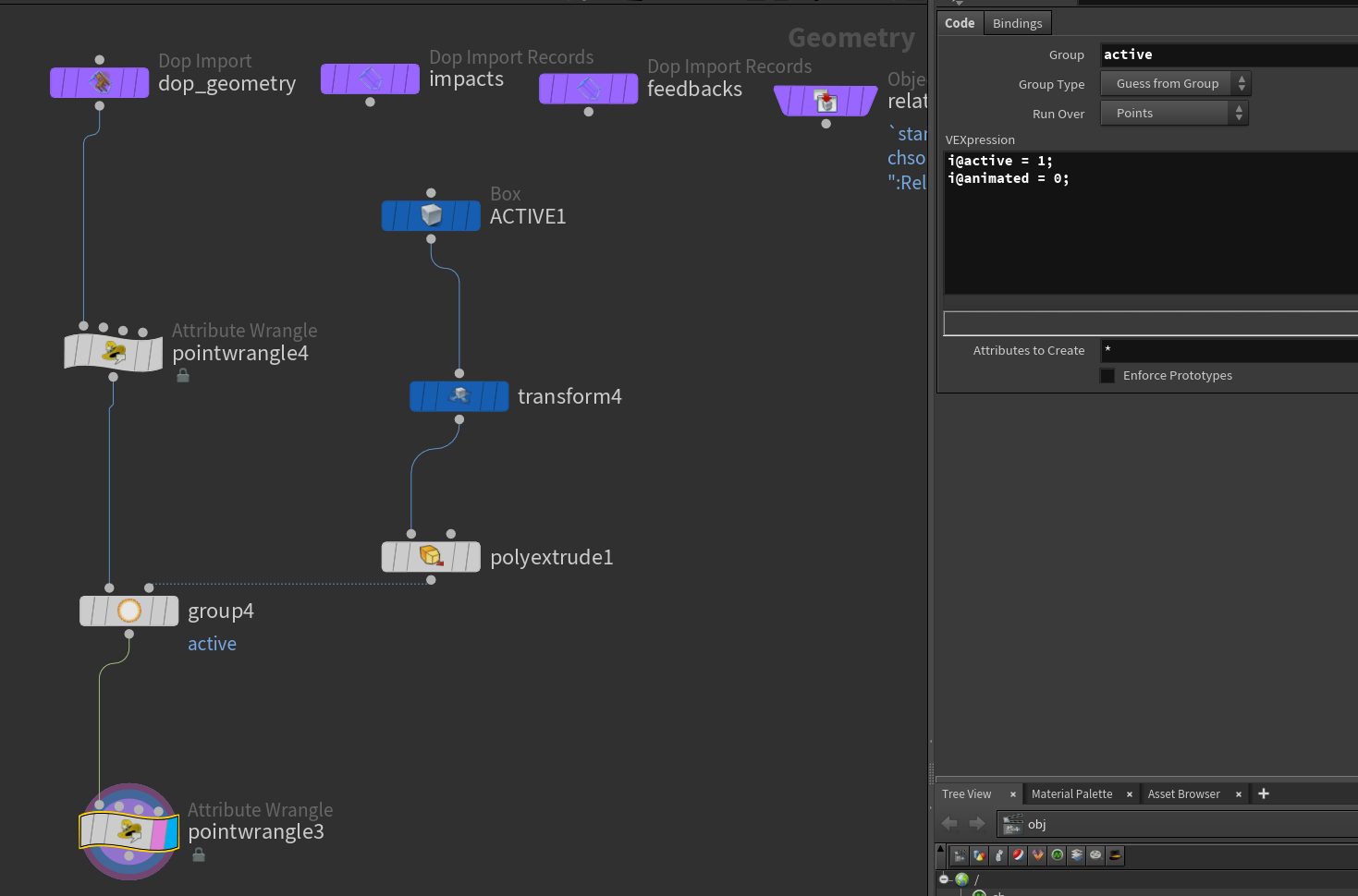
Activate animated geometry inside sopsolver
The vellum simulation setup
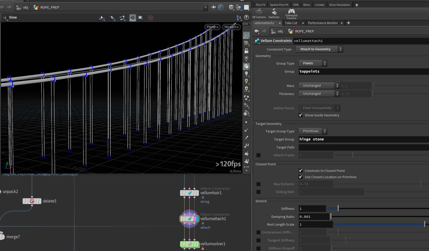
The vellum sim can be divided into two parts: the wires that are not broken and the foreground broken ones. First, two groups of points are created to identify where are needed to be connected to the bridge surface. The upper group is connected to the main suspension string, and the simulation of this string is based on RBD simulation with glue constraints. Because the glue constraints value is set to -1, they cannot be broken anymore. The string will hold for the entire time with a little random movement, which is excellent. Once finished the string simulation, we could use vellum type "attach" to create the target geometry——the main suspension string, and the "string" type for setting up vertical wire properties.
The main suspension string simulation
The vertical wire vellum settings
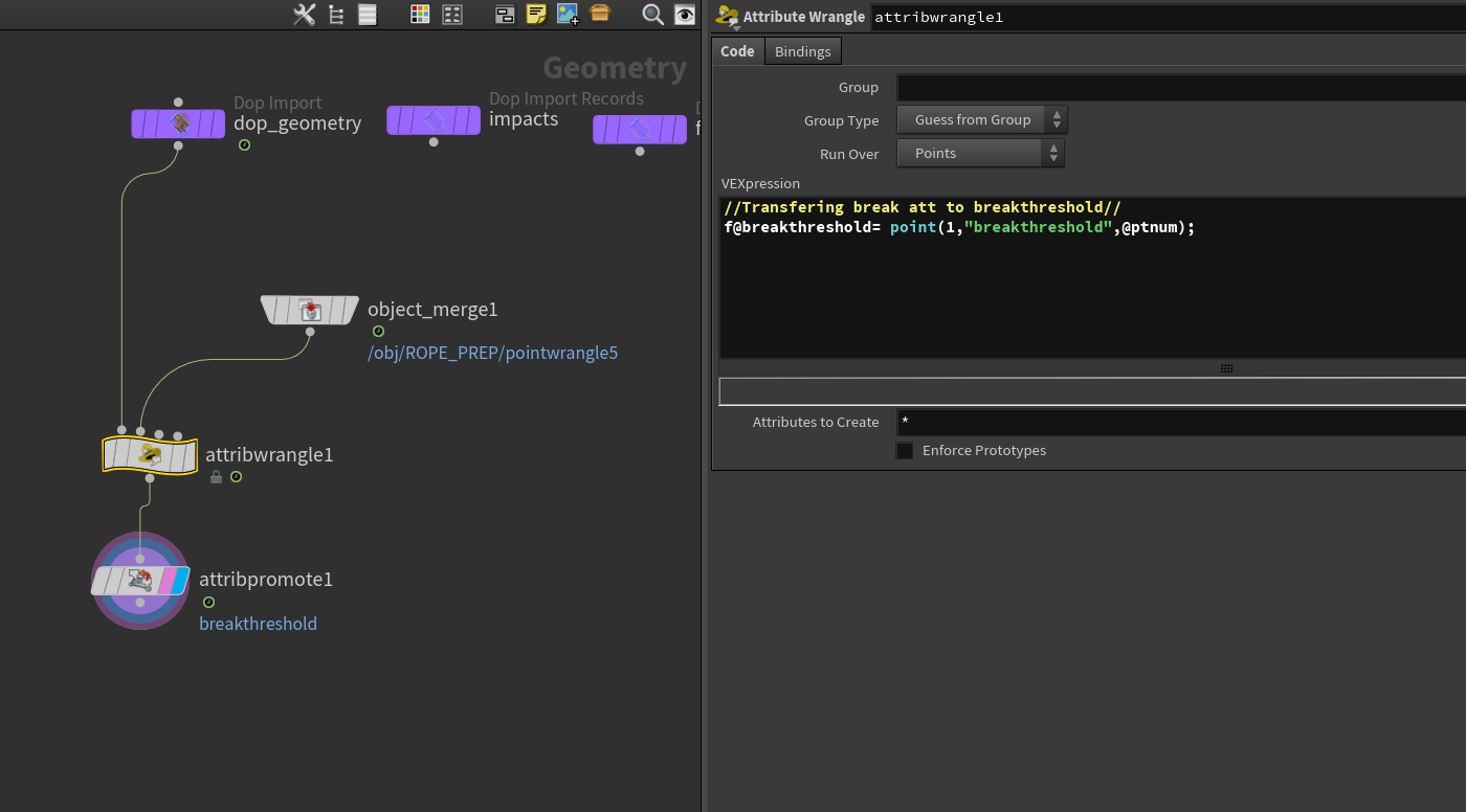
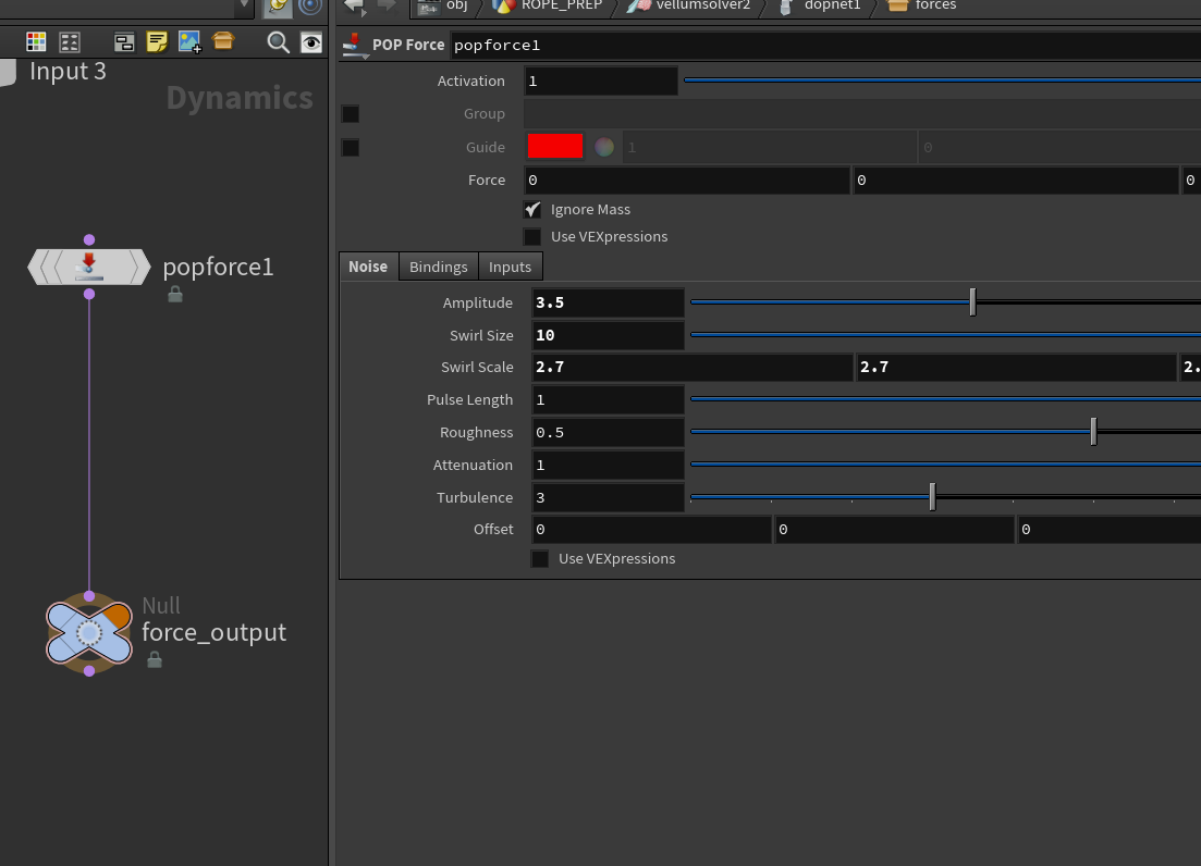
Inside the vellum solver, the constraint iterations number increased to 500 to ensure a better and more stable result. To sync with the main structure timing, the manual activation for breaking vellum wires is required as the uniform breaking threshold may result in the wires breaking randomly. To achieve this goal, a sop solver is attached to the vellum solver for transferred the "break threshold" to the vellum constraint geometry in the DOP network. Also, a pop force with offset is added to the vellum network to ensure the wire itself has some initial horizontal movement before it breaks. In the vellum post-process, we can use the "poly wire" node to increase the wire radius and copy some steel parts to the wires' bottom.
Customize vellum constraint geometry
Pop force for vellum initial status
Debris Simulation
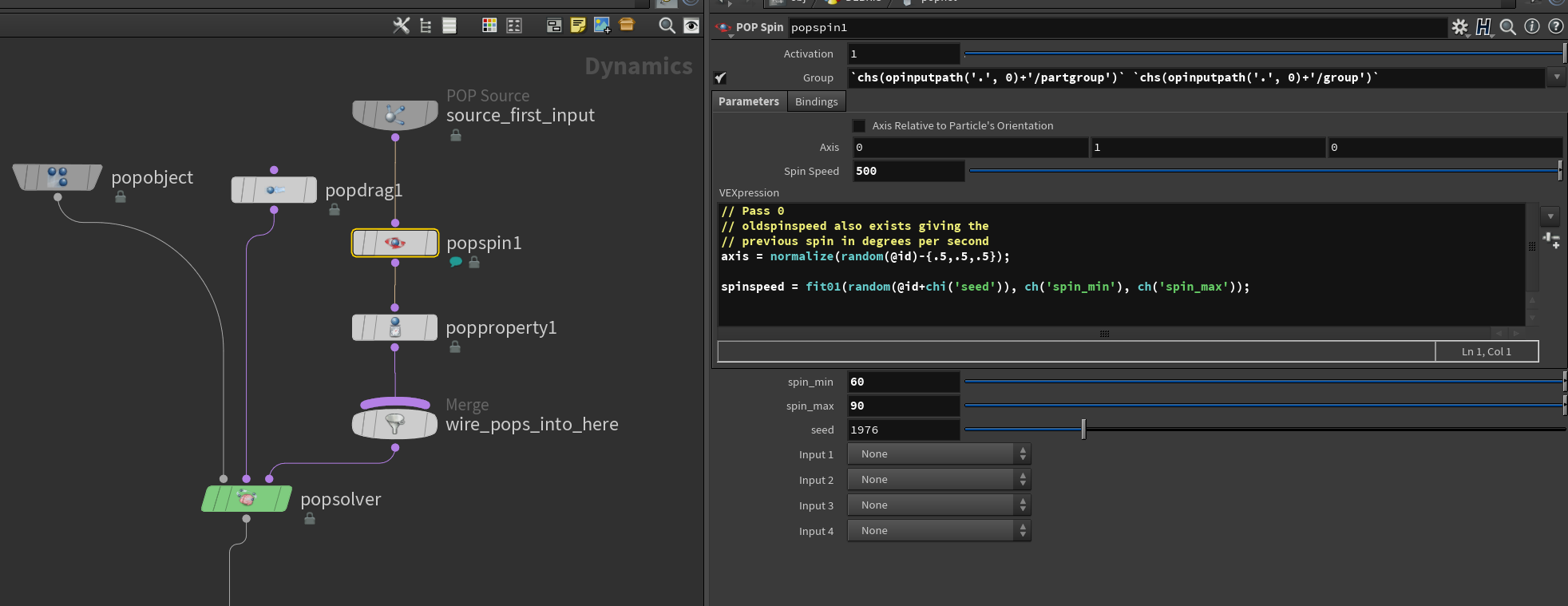
After the main structure, RBD simulation is finished, we can extract the road surface only for the debris source. The default "debris source" node provides useful controls for customizing debris emission. To have more stylized control on the density and scale of individual debris, a point wrangle is attached before caching out the debris source. In the debris DOP simulation, the particles are assigned random rotation speed and a small-scale pop drag. The debris instance is generated from two different types: metal pieces and concrete ones. After the particle cache progress is finished, we can randomly copy the instance to the points and assign different shaders.
Debris simulation configures
Smoke Simulation
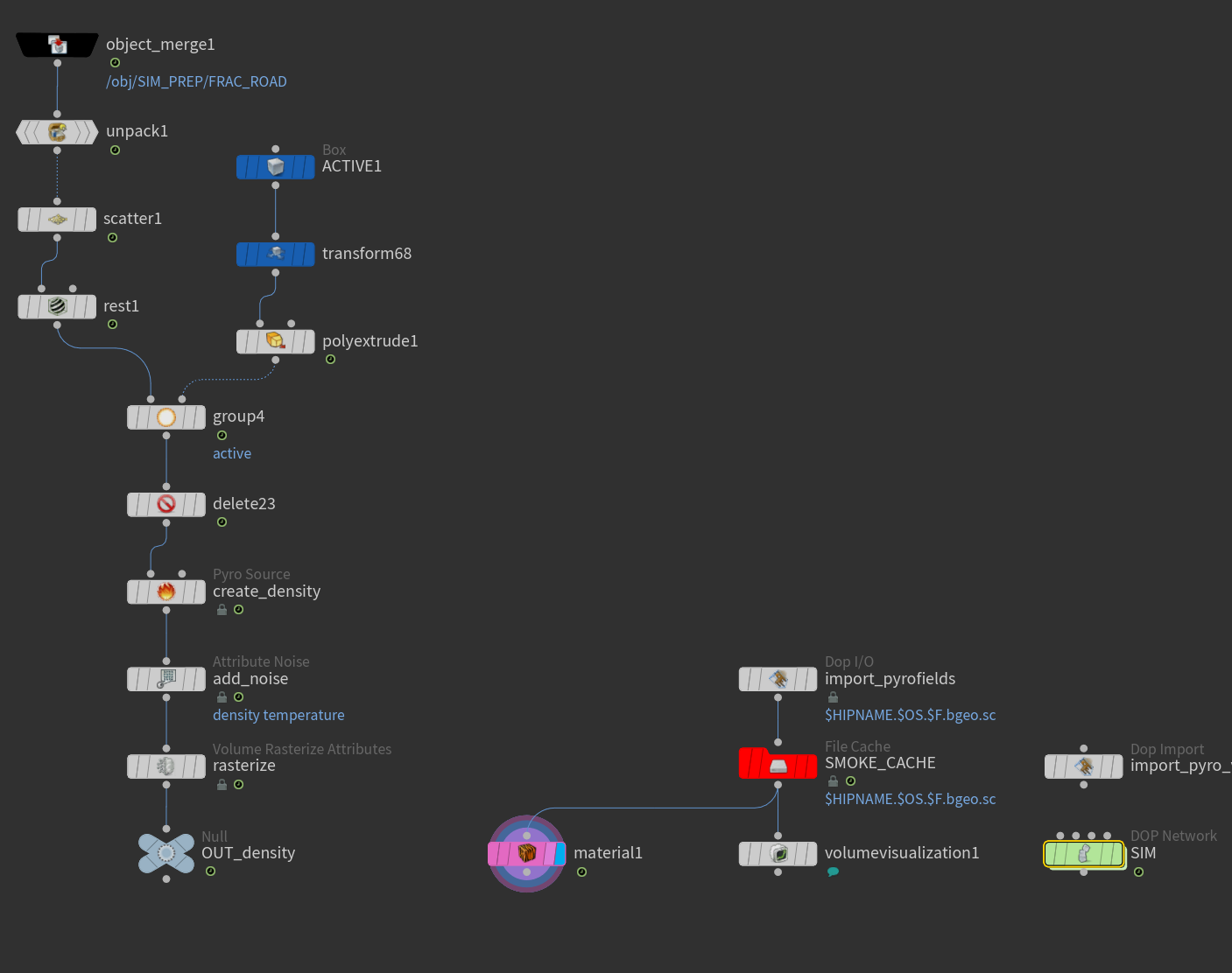
The vital part of the smoke simulation is to customize the smoke source properly. In this project, we need the smoke to follow the primary structure RBD simulation also. Therefore, the road surface is also extracted from the RBD cache independently to emit the smoke. The activator for the primary RBD simulation can also be used for deleting unnecessary parts. Then, the smoke source will be modified based on particle separation as well as coverage scale. Inside the smoke DOP network, the dissipation value is significantly increased as the smoke would just remain a few seconds when it appears. Also, the disturbance value and turbulence value are slightly increased to give the smoke a little "wild" appearance.
Smoke simulation setup
Ocean surface setup
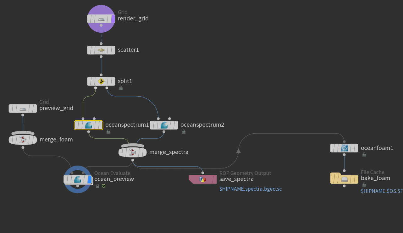
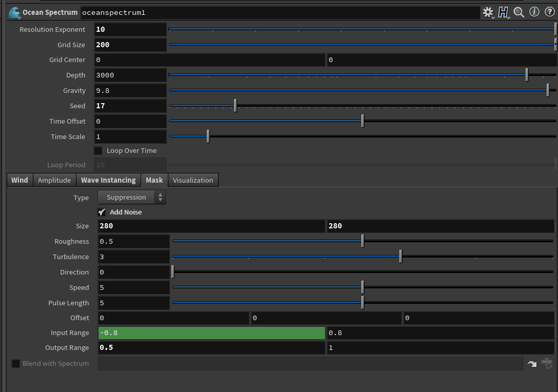
For the water surface, it is a standard shelf tool setting for large ocean surface. The water surface spectrum has a high frequency from the cam angle, while the whole movement along the direction is not apparent. To achieve this look, both ocean spectrum has been adjusted to match the reference. After caching out the spectrum geometry and it's ready for rendering.
Water surface settings
Ocean spectrum settings
Results and further improvements
The general purpose of this project is to recreate the suspension bridge destruction scene through different modules. By combining several dynamic simulation techniques, plenty of elements in the reference video are presented successfully. However, there are still many improvements needed for further revision, such as the traffic light should be detached later before the main bridge structure moves. Furthermore, if the crowds simulation on the bridge exists, it would add more realism to the whole scene.
One thought on “Bridge Destruction”
Love to see your case study, is it possible to have base explanation file which help us more to understand workflow.

Love to see your case study, is it possible to have base explanation file which help us more to understand workflow.